
In particular I got involved in interesting single-lever paddle design proposed by A. Pershin RV3AE (http://forum.qrz.ru/post747010-2847.html, http://forum.qrz.ru/post747473-2855.html). The main problem of a single lever paddle is "bouncing", and this design not only eliminates possible bouncing, but also provides a definite-feeling center position. Sketches below illustrate the idea which consists of use of a single magnet placed behind the brass "insert" freely suspended in the frame of brass or aluminum alloy. It works as follows.
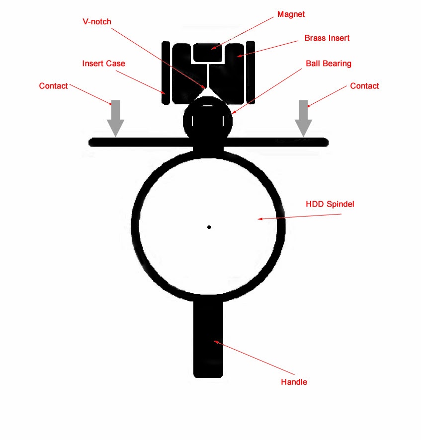


The insert has a vertical frontal V-shaped groove, across which a small ball bearing, mounted at the end of the paddle’s lever, can roll. The attraction force of a magnet placed behind the insert holds the ball bearing at the center of the V-shaped groove. When the ball bearing moves across the groove, it pushes the insert backward, increasing the distance between the magnet and the ball bearing; the magnetic force then tends to return it to its original position. Thus, with proper selection of magnet strength, magnet placement, and groove geometry, the paddle operates without “bouncing”—the major drawback of single-lever paddles—and the center position is firm and well defined.
The rectangular insert is freely suspended on the cones (or solid axis) inside of the frame made in my case out of a segment of a square aluminum profile approximately 3/4” long with the internal opening of 1/2” x 1/2” and the wall thickness of 1/8”.
The thickness of the brass insert is chosen to be 1/4” and the width of it is a little smaller (about .004"-.005") than 1/2” opening which allows it freely fit and hang into the internal opening of the frame but without noticeable play. The insert’s vertical size should be about 1/16” shorter than it’s width which allows insert freely hangs and moves inside the frame.
The insert should be drilled together with the frame (segment of the aluminum profile) to ensure proper alignment of the holes. To do this auxiliary hole should be drilled in the front bottom of the center of the profile and this hole should be threaded (for example, metric M4). Then the insert should be firmly clamped inside the frame using the appropriate size screw which threads into this hole. The entire assembly should be drilled then transversely with the drill bit of the diameter of about 1.5mm. The M4 threaded hole at the bottom of the frame is being used later to fasten the whole assembly to the base of the paddle. The holes on both sides of the frame should be reamed to needed diameter and be threaded for cones (for cones I used appropriate size of set screws found in my junk box).
The V-shape groove in the insert is being cut using triangular file to the depth of about 1.5mm, then auxiliary hole (with the diameter of about 1.0-1.5mm) drills through the center of the groove at the bottom of the insert, then from the back of the insert this hole should be reamed to the diameter of cylindrical magnet to the certain depth (not fully through the insert!). The distance from the ball bearing to the magnet and its magnetic power determines proper function of the entire system. V-shaped groove (especially the edges) should be rounded slightly using needle files and polishes with very fine sandpaper. All this is being done during final assembly and adjustment.
The force of magnetic attraction (i.e. the force on the paddle’s lever) can be adjusted if necessary by use of the nonmagnetic washers, being placed under the magnet increasing the distance to the ball bearing. These washers may be made out of a thin plastic or even thick paper (which I actually used). This adjustment procedure looks cumbersome but you do it once (or not often) and it’s not really complicated.
Photo below shows this insert in the assembly separately from the rest of the design, the ball bearing stays in the shown position by the force of attraction of the magnet.


1 comment:
Great! I might try making one for myself.
Post a Comment